Arduino Relay Board Basics
In the example an Arduino Nano is used ... examples also apply to Arduino Uno.
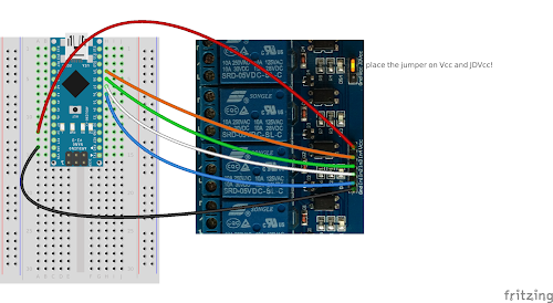
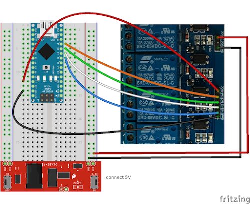
The first setup uses the Arduino power to switch the relay ... the second setup explains the JDVcc setting to use an external power source for the relay.
Load the 4 relay switch sketch to the Arduino
// Basic 4 Relay board connection
// Each relay is turned on for 2 seconds and then off.
// You can hear them click as the state changes from off to on and on to
// off.
// You will also see the corresponding Red LED on the 4 Relay board
// light up when the relay is on.

 //  define names for the 4 Digital pins On the Arduino 6,7,8,9
 //  These data pins link to 4 Relay board pins IN1, IN2, IN3, IN4

 //!!!place jumper over Vcc and JDVCC...leave Gnd open!!

#define RELAY1  6
#define RELAY2  7
#define RELAY3  8
#define RELAY4  9

void setup()
{
// Initialise the Arduino data pins for OUTPUT
  pinMode(RELAY1, OUTPUT);
  pinMode(RELAY2, OUTPUT);
  pinMode(RELAY3, OUTPUT);
  pinMode(RELAY4, OUTPUT);
}

 void loop()
{
   digitalWrite(RELAY1,LOW);           // Turns ON Relays 1
   delay(2000);                                      // Wait 2 seconds
   digitalWrite(RELAY1,HIGH);          // Turns Relay Off

   digitalWrite(RELAY2,LOW);           // Turns ON Relays 2
   delay(2000);                                      // Wait 2 seconds
   digitalWrite(RELAY2,HIGH);          // Turns Relay Off

   digitalWrite(RELAY3,LOW);           // Turns ON Relays 3
   delay(2000);                                      // Wait 2 seconds
   digitalWrite(RELAY3,HIGH);          // Turns Relay Off

   digitalWrite(RELAY4,LOW);           // Turns ON Relays 4
   delay(2000);                                      // Wait 2 seconds
   digitalWrite(RELAY4,HIGH);          // Turns Relay Off
 }
Wire instruction
Leave the jumper on Vcc and JDVcc
Using external power
In the wire instruction below we use a breadboard power system to power the rails, however any external 5V power could do the same.
Also note that the Arduino Nano is seperated from the breadboardpower!
Wire instruction
Small test
We leave the same sketch on the Arduino.
Check how the Arduino still powers the leds on the relay board when external power is detached (no click sounds).
Turn on the external power again and the relays start to switch.
This example shows how the Arduino sketch triggers the relayboard led's ... the relayboard triggers the relay when a led is "High"
Labels: Arduino-relay