ATtiny/Dice Shield
The female headers on the Proto 0.03 board are allowing easy placements of addon-shields. A shield for the ATtiny board needs to be simple since the pins on an ATtiny are limited, however a few pins is all we need to play with.
Dice Shield 0.01
An electronic dice needs to have 7 leds but since we can combine the leds in 3 pairs and a single led (4 pins in total) we have room for a push button to activate the dice and show a random number (1 to 6).
The Dice Sketch
Binary sketch size: 2,002 bytes (of a 8,192 byte maximum) just a quarter of the space ...
/*
  ATtinyDiceshield
  Boardtype is ATtiny85 @ 1MHz (internal oscilator, BODdisabled)
*/
int pinLeds1 = 3;
int pinLeds2 = 2;
int pinLeds3 = 1;
int pinLed4 = 4;
int buttonPin = 0;
int buttonState;
long ran;
int time = 1000;

void setup ()
{
  pinMode (pinLeds1, OUTPUT);
  pinMode (pinLeds2, OUTPUT);
  pinMode (pinLeds3, OUTPUT);
  pinMode (pinLed4, OUTPUT);
  pinMode (buttonPin, INPUT);
  randomSeed(analogRead(0));
}

void loop()
{
  buttonState = digitalRead(buttonPin);
  if (buttonState == HIGH){
    ran = random(1, 7);
    if (ran == 1){
      digitalWrite (pinLed4, HIGH);
      delay (time);
    }
    if (ran == 2){
      digitalWrite (pinLeds1, HIGH);
      delay (time);
    }
    if (ran == 3){
      digitalWrite (pinLeds3, HIGH);
      digitalWrite (pinLed4, HIGH);
      delay (time);
    }
    if (ran == 4){
      digitalWrite (pinLeds1, HIGH);
      digitalWrite (pinLeds3, HIGH);
      delay (time);
    }
    if (ran == 5){
      digitalWrite (pinLeds1, HIGH);
      digitalWrite (pinLeds3, HIGH);
      digitalWrite (pinLed4, HIGH);
      delay (time);
   }
   if (ran == 6){
      digitalWrite (pinLeds1, HIGH);
      digitalWrite (pinLeds2, HIGH);
      digitalWrite (pinLeds3, HIGH);
      delay (time);
   }
  }
  digitalWrite (pinLeds1, LOW);
  digitalWrite (pinLeds2, LOW);
  digitalWrite (pinLeds3, LOW);
  digitalWrite (pinLed4, LOW);
}
Breadboard setup

Perfboard
Fritzing is also great for the perfboard test setups.
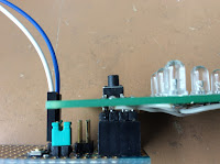
Using the ATtiny as component at the side we can make things match properly (move in and move it aside again). This is mainly to focus on the push-button which is best placed on top of the ATtiny in the center of the headers since it gets some force from human interaction.
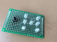
The final placement of the leds is done on the actual board by equally using the available space (placement in the image is used as reference).

List of materials
| Item | Pieces | ||
|---|---|---|---|
| Perfboard * | 14x20 holes | ||
| Push button | 1x | ||
| Led | 7x | ||
| 10 k Resistor ** | 1x |
* best experience with trough hole soldering pads
** brown black orange
The Dice Shield 0.01 finished
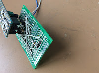
| Top | Bottom | ||
|---|---|---|---|
 |
 |
| Line up | Snap in place | ||
|---|---|---|---|
 |
 |
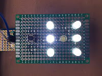
| Button on top of the ATtiny | Six \o/ | ||
|---|---|---|---|
 |
 |
Labels: ATtiny